Minggu, 12 Mei 2013

Memperbaiki Rice Cooker, Rice Magic Jar, Cooker Youngma

Rice Cooker Komponen Utamanya yang sering mengalami kerusakan :
1. Elemen Pemanas ( jarang rusak kadang-kadang aja)
2. Pengontrol Panas termostat atau alat pengukur panas (sering rusak langsung ganti yang baru)
3. Temperatur Fuse.- Thermofuse (sering rusak ganti yang baru)
4. Kabel Colokan ( kabel putus ditengah cek dengan multitester dan ganti kabel yang baru)
5. Kabel di dalam rice cooker putus dan lepas dari timahnya. Anda ingin tahu, selanjutnya..

Ciri-ciri Rice Cooker Mati Total :
>Rice Cooker Sama sekali Tidak Panas Setelah dinyalakan 1-15 menit alias mati.
>Lihat lampu Indikatornya tidak menyala Sama sekali yakni Lampu Indikator buat Menghangatkan Nasi dan Memasak Nasi alias Mati Total.

Cara Memperbaikinya :
*Ambil Rice Cookernya, bukalah tutup rice cooker dibagian bawah dengan alat obeng minus dan plus.
*Ambil Multu tester Cek Fuse derajat Celsius .Bila hasilnya 0 (Nol) multitesternya tdk bergerak waktu di *cek berarti Fuse derajat Celsius mati total
*Ganti Fuse  derajat Celsius dengan yang Baru.
*Tutup kembali tutup Rice Cooker bagian bawahnya.
*Cek dengan Menyalakan rice cooke di stop kontak hasil oke.

Ceri-ciri Rice cooker apa aja Bila *Nasi yang dimasak Jadi Berbau bewarna kuning dan **Nasi Lembek berair
*Cara memperbaikinya Ganti Thermostat (merek nya sama) yang lama dengan yang baru
Thermostat adanya disebelah elemen samping dalam atau dibagian bawah rice cooker.

**Cek elemen penghangat bagian tutup atas berupa lingkaran dengan tangan, bila tidak hangat berari rusak
Cara perbaikinya cek kabel yang kecil disana siapa tahu adad yang putus bila tdk ada berarti elemen penghangat atasnya tidak berfungsi ganti yang baru atau anda mau utak atik siapa tahu bisa.

MEMPERBAIKI MAGIC JAR

PART :
1.Lampu 2 buah (Sebagi Tanda) : 1.Power 2. Warm
2.Thermostate (Sebagi Mandor) / Control / Pemutus hubungan panas
3.Elemen Body (Sebagi Pekerja) / Penghangat
4.Elemen Tutup (Sebagi Pekerja) / Penghangat
5.Kabel Penghubung
 
SISTEM KERJA :
Saat kabel dicolokin kelistrik kedua lampu langsung nyala,kedua elemen (Bodi dan Tutup) langsung bekerja (Panas), Nah Thermostate mengontrol kadar panas pada bodi magic jar,karena pada suhu tertentu/jika panas sudah cukup,Thermostate akan menghentikan atau memutuskan aliran listrik ke elemen tersebt sehingga elemen tidak bekerja lagi.Tapi jika panas didalam tempat nasi/bodi sudah tidak panas lagi maka Thermostate akan menghubungkan kembali aliran listrik ke elemen dan elemen bekerja lagiiiii untuk memanaskan bodi .begitu seterusnya.
 
KELUHAN :
1. Nasi basi/kuning/bau dan sejenisnya
2. Nasi kering dan sejenisnya
 
CARA MEMPERBAIKI :
1. Jika Nasi basi/kuning/bau dan sejenisnya
1. Buka baud magic jar yang ada di pantat/dibagian bawah magic jar
2. Setelah baud terlepas lalu penutup pantat magic jar dengan cara karate bodi magic jar dengan kedua tangan
3. Setelah terbuka disamping bodi bagian dalam akan terlihat thermostate (bentuknya kaya kancing) dalam posisi terjepit.coba selipkan kertas tebal (kertas bekas pembungkus power glue) sebanyak tiga lipatan .lalu pasangin deh tutupnya.coba dechhhh.Gampangkan!!!!,

MENGENAL, MERAWAT, DAN MEMPERBAIKI PENANAK NASI ( RICE COOKER )

PENANAK NASI LISTRIK (ELECTRIC RICE COOKER)
Alat penanak nasi yang banyak dipakai pada rumah tangga umum menyebutnya rice cooker. Dan karena waktu penanakannya cukup lama ya kira-kira 1,5 jam, alat ini disebut juga sebagai slow

Cara Service Kipas Angin yang Tidak Berputar dan Berdengung

Artikel ini adalah kiriman dari teman kang Eko yg ada di Jakarta sana. Namanya bang Riko, Alhamdulillah bang Riko mau menyumbangkan ilmunya di blog kang Eko ini. Kali ini yg akan dibahas bang Riko adalah tentang cara servis kipas angin yang tidak mau muter. Berikut ulasan dari bang Riko….
Setelah mendapatkan servisan kipas angin minggu lalu, bang Riko mencoba berbagi ilmu diblognya kang Eko ini. Jika anda menjumpai kipas angin yang ngga bisa muter dan bahkan hanya berdengung / bergetar saja. Ngga usah buru2 membuangnya. Karena masih mungkin bisa anda perbaiki sendiri.
Sebenarnya kerusakan ini timbul dikarenakan oleh laher/bearing yang sudah aus. Sehingga mengakibatkan as kipas menyentuh liner kern.
Cara Service Kipas Angin yang Tidak Berputar dan Berdengung :
1. Bongkar kerangka kipas angin beserta baling balingnya. Serta buka baut yang mengikat kerangka gulungan/spul kipasangin secara perlahan dan hati2 jangan sampai kabel penghubung dengan gulungan terputus, karena akibatnya bisa fatal bila anda tidak bisa menemukan / menyambung kembali kabel yang putus.


2. Lepaskan bearing dari rumahnya, dan coba perhatikan apakah benar telah terjadi ke-ausan pada liner bearing tersebut jika benar, berarti bearing harus diganti. bearing ini banyak dijumpai di pasaran dan harganya pun relatif murah.


3. Setelah bearing diganti, sebelum kita menutup kembali (merakit kipas) tidak ada salahnya jika kita bersihkan semua kotoran yang menempel, caranya dengan menggunakan tiner atau bensin tapi jangan lupa sebelum dirakit harus kering dari bensin atau tiner. Yang paling utama adalah Bersihkan as kipas angin dengan kain yang bersih, kemudian berikan sedikit baby oil atau paslin (jangan terlalu banyak dan hanya asnya saja) yang terpenting permukaan as yang berhubungan langsung dengan laher/bearing terlumasi.
4. Setelah semuanya bersih dan dirangkai, kipas siap di coba.. hasilnya huftttttttt dingin bos..
Selamat mencoba..

Sabtu, 11 Mei 2013

555 Timer-Based Flyback Transformer Driver Posted by leorick at 9:04 PM

My 24kV high voltage "Jacob's Ladder" from DIY flyback transformer driver using 555 timer.

Creating an electric arc

I've always wanted to create an electric arc but don't know how. Then I come across the theory that air breaks down at about 1MV/m (Mega Volts per meter) (24kV/in). That mean you need 1kV in order to get 1mm arc. So you need a higher voltage. One of the method is to use a flyback transformer that can be found from an old TV or an old CRT PC monitor. It could generate about 10 to 30 kV. Other method is to create a "tesla coil" which is quite complicated. Maybe it will become my next project.

Flyback transformer and preparation

Flybacks can be found in all types of monitors and screens that use a cathode ray tube (CRT), e.g. TV sets, computer monitors etc. It has a big red cable with a suction cup. It looks something like below.

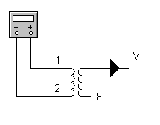
Next, you need to identify the primary and secondary pin out. Thanks to "Lab HV-PS page" for providing an instruction on how to find the pinout. The main HV out on the secondary coil is a big red cable with a suction cup. Now we need to find the 0V pinout for the secondary coil. The trick is to use a DC power supply. This is because the flyback secondary coil resistance is much too high. There is no way you could find it with ordinary digital multimeter.

So use your own understanding on the circuit below to find the 0V pinout. Give it about 12V and your meter should show some volts when you find the 0V pinout. For me, just to be safe, try to find a datasheet of the flyback transformer or try to find the TV or old CRT PC monitor service manual/schematics diagram to find the pinout like below. Most modern flybacks include built-in HV rectifier diode(s) and/or voltage multiplier (tripler) so output without additional components will be high voltage positive or somewhat smoothed HV DC. So, make sure your polarity is correct.

Unless you have one of these multimeter, you should get the resistance reading out of it. From my FLUKE 189 multimeter you can see that it shows more than a hundred Mega Ohm. That is why ordinary meter could not measure it because of it's limit. Below I test two types of flybacks with 112 Mega Ohm and the other about 522 Mega Ohm. Again, polarity is critical to get the reading.

To find the primary coil is a much simple than the secondary coil. The primary coil resistance is about 1 ohm and again I confirm this with a TV or old CRT PC monitor service manual/schematics diagram. In my case I could only get 0.45 ohm.

Creating the flyback driver (20kHz with 90% duty cycle)

Thanks to "Jonathan Filippi" for the idea. My circuit is quite different. I try to fix up the frequency and duty cycle with help from simulation software. I use "Electronic Workbench" to simulate the circuit which can generate about 20kHz with 90% duty cycle and I come out with this. Using 555 timer to generate 20kHz with 90% duty cycle. Next I try to put it on the breadboard and test the output from it. I get about 18kHz with 85% duty cycle. Jonathan Filippi is using 2N3904 and 2N3906 but I'm using c1815 (npn) and a1015 (pnp). I found out that you can use any multipurpose transistor and I could find it on my old TV board. For the MOSFET, Jonathan Filippi is using IRF840 but I'm using IRF630. You may try to find it's equivalent and experiment with it. Just make sure it is compatible if you want to use other types of MOSFETs. Find it's data sheet and compare the characteristic for both types of components.

Before assemble it, I test this circuit with a small transformer which I can find it on the same old TV board. Since I'm getting too excited, the quick test is to connect the output to the lowest resistance coil. I test it with a limit resistor and surprise, I can get a hundred volt out of that.

Next is to plan to transfer it to the stripboard/veroboard. Here is the stripboard layout and the assembled circuit board. Make sure you mount the MOSFET to a heat sink since it going to heat up while running/powering it up. Note that I put the 150 ohm "snubber" resistor and diode near the flyback. This is to suppress ("snub") electrical transients that might damage of the circuit.

Again, I test the assembled circuit board with the same small transformer and I could get a neon to light up. This mean I'm getting about hundred volts. Neon needs about 80V or higher in order to light up.

Test it out

Now it time to test it out. Get a high power supply for this test. Don't use an expensive lab power supply for this test. It might burn or damage. For me, I'm using a 12V DC battery charger that can give about 5 Amps. You may also try a car battery if you have one.

There is an arc!. At last, I could get an arc out of it. I try to measure the initial max. length and I could get about 24mm. Thus, it is about 24kV. Remember the theory 1MV/m?.


I measure the DC operating current. It is about 5 Amps. I've blown my DC power supply fuse in the process. Maybe I need a bigger power supply :-) . At least I've got some arcs.

https://blogger.googleusercontent.com/img/b/R29vZ2xl/AVvXsEiVZHcj_E_q4H4Md2n8r4vRsbOzf-rgusPGawPuoj_g6KsoMFB1MIvMKQx3W2vWcHHMCfr-WG39OfUM0xESKn5Y557kIfROdqlI845vi49Byd03o4PXkqWUU89KNTUgwp7Zo0vpxcuQVcdy/s1600/schDuringTesting.png

Good luck!

Flyback Driver circuit

This is a instructable that contains scematic and pictures of a single transistor flyback driver.

stuff's used:

1x breadboard
1x NPN transistor (with heat sink and a fan)
1x 22 Ohm resistor
1x 220 Ohms resistor
1x transformator (or round ferrite core) with same amount of windings
1x flyback transformator
1x 12 - 15V Powersupply ( i use a battery that gives 15 volt, 400 mA)

And some wires.

Step 1: Scematic of the driver

After i tryed the flyback driver with the primary and feedback windings on the flyback's ferrite core, i thought: *why not try t o use a tiny transformator with same amount of windings to oscillate the process, and so i found out i would try it, and  i got 10 - 15Kv More from the flyback transformator by doing this, so i figured i would make an instructable.

i think the picture is somewhat blurry cause of the size, so il point out the important stuffs here:

* The transistor must have a heat sink.

* Before you put 12 volt in, test the circuit with 3 - 6 volts, and make shure that the transistor doesn't get overheated
(I currently run the circuit with 15 V , 400 mA, and still i cannot feel any sign of heat on the transistor)

i get around 50 Kv from this.

SKEMA TESTER FLYBACK

Bagi rekan-rekan teknisi TV atau Monitor tentunya sering mengalami/menemui Flayback yang rusak,
Namun kadang masih ragu untuk memastikan apakah flyback tersebut memang benar-benar rusak.
Seperti yang sering saya alami dalam melakukan perbaikan TV atau monitor.

Dari hasil pencarian berbagai sumber yang saya akhirnya timbul ide untuk membuat sendiri rangkaian Flyback Tester ini. Selain untuk ngetest Flyback rangkaian ini ternyata juga bisa digunakan untuk sebagai "CRT Restorer".

Biar lebih jelas berikut skema rangkaiannya :[FBT+tester.JPG]


dasar dari rangkaian ini adalah rangkaian osilator seperti yang biasa digunakan pada rangkaian inverter/noen dc.outputnya L3 (lilitan sekunder) diumpankan lagi ke basis transistor D313.TR1 transistor bekas horizontal driver.

untuk liltan L1-L3 tidak perlu susah-susah membuat lilitan baru.Hal ini bisa dilakukan dengan mengambil dari bekas trafo Horizontal TV/Monitor dengan sedikit modifikasi.
berkut cara Modifikasi Trafo bekas horizontal driver untuk digunakan pada rangkaian flyback tester ini.
1. siapkan trafo bekas horizontal driver
2. buka isolator pembungkusnya,kemudian lepaskan/bongkar inti ferrite-nya.hati- usahakan jangan sampai pecah/rusak karena nantinya inti ferrite akan digunakan lagi.
3.lepaskan lilitan paling luar/lilitan sekundernya,hitung dan catat jumlah lilitannya.Untuk lilitan Primer tidak perlu dibongkar.
4.ambil kawat email dengan diameter kawat sama dengan diameter lilitan primer
5.lilitkan dengan rapi dengan posisi diatas lilitan primer(biasanya antara 15-20 lilit),lilitan ini digunakan sebagai feedback-nya (L2) agar rangkaian bisa berosilasi,jangan lupa perhatikan arah lilitannya.karena jika terbalik rangkaian tidak akan berosilasi, namun jangan panik. tinggal tukar saja kaki-kaki lilitan feedbacknya(L2).
6. setelah lilitan fedback selesai lanjutkan dengan melilitkan ulang kawat lilitan sekunder yang tadi dilepas, modifikasi selesai.