My 24kV high voltage "Jacob's Ladder" from DIY flyback transformer driver using 555 timer.
Creating an electric arc
I've
always wanted to create an electric arc but don't know how. Then I come
across the theory that air breaks down at about 1MV/m (Mega Volts per
meter) (24kV/in). That mean you need 1kV in order to get 1mm arc. So you
need a higher voltage. One of the method is to use a flyback
transformer that can be found from an old TV or an old CRT PC monitor.
It could generate about 10 to 30 kV. Other method is to create a "tesla
coil" which is quite complicated. Maybe it will become my next project.
Flyback transformer and preparation
Flybacks can be found in
all types of monitors and screens that use a cathode ray tube (CRT),
e.g. TV sets, computer monitors etc. It has a big red cable with a
suction cup. It looks something like below.

Next, you need to identify the primary and secondary pin out. Thanks to "
Lab HV-PS page"
for providing an instruction on how to find the pinout. The main HV out
on the secondary coil is a big red cable with a suction cup. Now we
need to find the 0V pinout for the secondary coil. The trick is to use a
DC power supply. This is because the flyback secondary coil resistance
is much too high. There is no way you could find it with ordinary
digital multimeter.

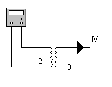
So use your own understanding on the circuit below to find the 0V
pinout. Give it about 12V and your meter should show some volts when you
find the 0V pinout. For me, just to be safe, try to find a datasheet of
the flyback transformer or try to find the TV or old CRT PC monitor
service manual/schematics diagram to find the pinout like below. Most
modern flybacks include built-in HV rectifier diode(s) and/or voltage
multiplier (tripler) so output without additional components will be
high voltage positive or somewhat smoothed HV DC. So, make sure your
polarity is correct.


Unless you have one of these multimeter, you should get the resistance
reading out of it. From my FLUKE 189 multimeter you can see that it
shows more than a hundred Mega Ohm. That is why ordinary meter could not
measure it because of it's limit. Below I test two types of flybacks
with 112 Mega Ohm and the other about 522 Mega Ohm. Again, polarity is
critical to get the reading.


To find the primary coil is a much simple than the secondary coil. The
primary coil resistance is about 1 ohm and again I confirm this with a
TV or old CRT PC monitor service manual/schematics diagram. In my case I
could only get 0.45 ohm.


Creating the flyback driver (20kHz with 90% duty cycle)
Thanks to "
Jonathan Filippi"
for the idea. My circuit is quite different. I try to fix up the
frequency and duty cycle with help from simulation software. I use
"Electronic Workbench" to simulate the circuit which can generate about
20kHz with 90% duty cycle and I come out with this. Using 555 timer to
generate 20kHz with 90%
duty cycle.
Next I try to put it on the breadboard and test the output from it. I
get about 18kHz with 85% duty cycle. Jonathan Filippi is using 2N3904
and 2N3906 but I'm using c1815 (npn) and a1015 (pnp). I found out that
you can use any multipurpose transistor and I could find it on my old TV
board. For the MOSFET, Jonathan Filippi is using IRF840 but I'm using
IRF630. You may try to find it's equivalent and experiment with it. Just
make sure it is compatible if you want to use other types of MOSFETs.
Find it's data sheet and compare the characteristic for both types of
components.


Before assemble it, I test this circuit with a small transformer which I
can find it on the same old TV board. Since I'm getting too excited,
the quick test is to connect the output to the lowest resistance coil. I
test it with a limit resistor and surprise, I can get a hundred volt
out of that.

Next is to plan to transfer it to the stripboard/veroboard. Here is the
stripboard layout and the assembled circuit board. Make sure you mount
the MOSFET to a heat sink since it going to heat up while
running/powering it up. Note that I put the 150 ohm "snubber" resistor
and diode near the flyback. This is to suppress ("snub") electrical
transients that might damage of the circuit.


Again, I test the assembled circuit board with the same small
transformer and I could get a neon to light up. This mean I'm getting
about hundred volts. Neon needs about 80V or higher in order to light
up.

Test it out
Now it time to test it out. Get a high power supply
for this test. Don't use an expensive lab power supply for this test. It
might burn or damage. For me, I'm using a 12V DC battery charger that
can give about 5 Amps. You may also try a car battery if you have one.

There is an arc!. At last, I could get an arc out of it. I try to
measure the initial max. length and I could get about 24mm. Thus, it is
about 24kV. Remember the theory 1MV/m?.


I measure the DC operating current. It is about 5 Amps. I've blown my DC
power supply fuse in the process. Maybe I need a bigger power supply
:-) . At least I've got some arcs.


Good luck!




![[FBT+tester.JPG]](https://blogger.googleusercontent.com/img/b/R29vZ2xl/AVvXsEgAHFtUv5v3j6tsbaMv6ChJAtKimBgi112G92ey3cx9LIIRbCY70VXhY6RK9SUy3UmcfMyp1XkShwgO88PH5Ws3BYjydf8IEA89SB49xjHtKnAwJ3hggvp4Y_Er6YmFb3bopASqTqozS_kq/s1600/FBT+tester.JPG)
